Zero to module: The making of Sycamore
Schematic walkthrough
- History and background
- EDA Software
- Microcontroller
- Power
- Bulk
- References
- Eurorack power
- Analogue inputs
- Potentiometers
- CV jacks
- Input scaling
- ADC & Pico
- Digital inputs
- Buttons
- Triggers
- Rotary Encoder
- Output
- DAC
- LEDs
- LED driver
- Other LEDs
- Mistakes, and learning from them
History and background
When Mutable Instruments was in the process of shutting down, Émilie Gillet started to publish a number of interesting bits of history about the company, technical details, design and aesthetic considerations and a few unpublished or unfinished projects at various stages of completion. Sycamore is based on a design by Mutable Instruments on their Cancelled Projects page.
You can think of Sycamore (And Seeds) a little like a quantized Turing Machine, with controls to guide the melodies produced, but without the full control of a more ordinary sequenencer.
Émilie open sourced the designs from Mutable Instruments, providing source code, schematics, and PCB layouts for people to iterate on. Keeping to the spirit of open source hardware, this is a dive into how the schematic for Sycamore came together.
Software
A few pieces of EDA and supporting software of note here:
-
Kicad 7 - for schematic design (And later, PCB layout)
-
CircuitJS - for simple component testing/prototyping, without touching a breadboard
-
Kicanvas - for embedding schematics into this document, and for quickly viewing other Kicad files online
Choosing a Microcontroller
Mutable Instruments modules used a variety of microcontrollers over the years, from the ATmega328 seen in Grids to powerful STM32 processors seen in many DSP-heavy designs. Sycamore doesn’t need a lot of processing power - enough to handle basic digital IO, and interaction with peripheral ICs. I also wanted the design to be easily hackable without too many special tools or a development environment.
Based on previous work with DrumFiend, I decided to go for a CircuitPython software stack. While DrumFiend uses the Teensy 4.0, a powerful and expensive microcontroller, I hoped to reduce the costs a little. The RP2040 microcontroller and the Raspberry Pi Pico in particular seemed like a good target, being well supported by Adafruit’s CircuitPython1.
For the schematic, I used a Rasperry Pi Pico Kicad library.
Here, I’ve just wired up +3.3v and +5v and added all the ground connections too. But where does the power come from?
Power
Broadly speaking, Sycamore has three different kinds of power: Power from the Eurorack power header, bulk power for LEDs/ICs/Pi Pico, and precision references.
Bulk +5v power
Let’s start with the power for the Pi Pico. I chose to use the LM1117, a low-dropout linear regulator which would easily supply enough power for everything I wanted. Linear regulators are generally preferred for their lower noise - that is, the amount of spiky voltage they may put into the output, or affect the input voltages. This regulator needs a few support components to work correctly.
The capacitors are a little different to what the datasheet suggests. To keep manufacturing costs a little lower, I standardised on 47μF electrolytic capacitors across the design as a decent middle ground between the 100μF recommended on the output side of the LM1117 and the 10μF on the input side.
The input for the LM1117 comes from the Eurorack power, which we will take a look at in a moment.
The output of the LM1117 feeds the Raspberry Pi pico 5v, which itself then transforms to 3.3v with an onboard voltage regulator.
Eurorack power
Eurorack’s power standard includes a 5v rail, a +12v, and a -12v along with ground. So why not use +5v from the case directly? Well, not all Eurorack cases come with +5v rails and I wanted to make sure the module worked with as many people’s cases as possible. This also has the advantage of using a smaller connector for power, which on a space-constrained board is definitely welcome.
The components consist of:
-
Ferrite beads2 to help reduce high frequency noise that might be produced by different parts of the circuit. PWM for LEDs, high-speed communications (I2C and SPI) can be problematic if not dealt with
-
Capacitors to act as a bulk power store
-
Schottky diodes, to prevent problems with reversed power cables. These save the day if a cable is plugged in the wrong way around, not allowing current to flow and destroy the module. Specifically Schottky diodes as these have a lower voltage drop than other kinds of power-handling diodes.
-
The power header itself, a 2x5 pin IDC connector
Voltage references
While we’re not quite at the DAC and ADC yet, it’s worth covering voltage references. These provide a very stable, very accurate voltage source for other ICs. They are not meant as power supplies themselves!
For Sycamore, as you’ll see a little later, I needed three different reference voltages: +5v, +3.3v, and -10v.
I chose the LM4040 precision micropower reference, mostly because I’d used it before, but also because it needs minimal external components to work correctly. Rather than depend on trimmable voltage references, I picked LM4040 varients which worked at 5v, 3.3v, and 10v to cover the three voltages required.
A couple of details are important here:
-
The -12v reference has the LM4040 connected “backwards” to provide the negative voltage required
-
Resistor values are a little different across each
The resistors in particular gave me some trouble. In prototyping, I used the same value across all three voltage references and one of them didn’t work at all! The datasheet, however, does give a calculation for checking the resistor value.
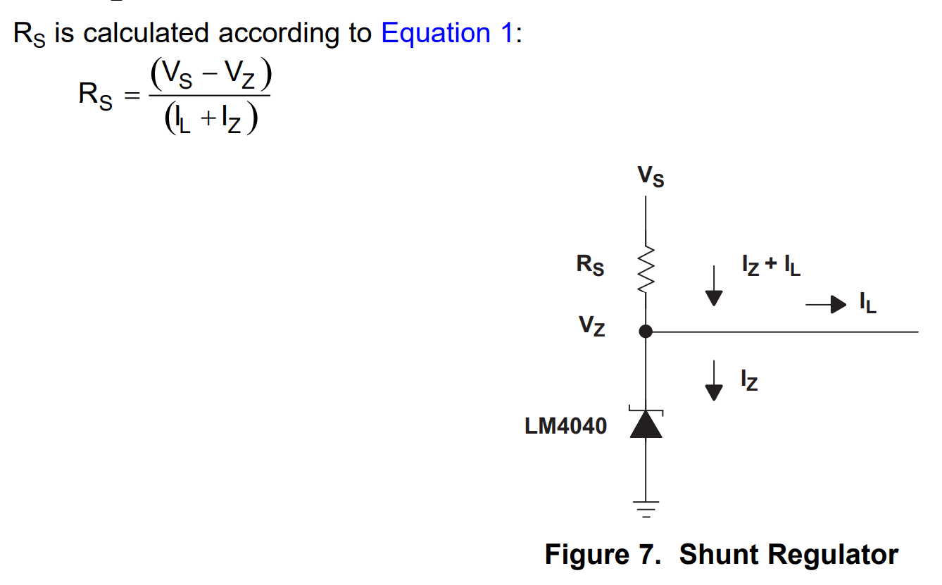
With Iz required to be at least 45μA and less than the absolute maximum of 25mA, there’s a pretty wide range of resistors that’ll work. I settled on some resistor values, mostly based on those used already in the design, and checked that the resulting current was within what the datasheet recommends.
Analogue inputs
Sycamore has a two different sets of analogue inputs: the potentiometers for manual tweaking, and the CV input jacks for external control.
In terms of design constraints, the analogue to digital converter (ADC), as you’ll see in a little while, wants values between 0 and 3.3v. So, both the potentiometers and CV3 inputs need to respect that.
Potentiometers
These are really simple - just potential dividers making anywhere from 0 to 3.3v. The value of the potentiometer doesn’t matter too much, I went for 10k as initially when testing, that’s what I had in my parts stash….
CV inputs
These are also fairly simple - just taking the input (In theory, anything up to -12v to +12v) from the jack and passing it along…
But what about those design constraints? The CV inputs need to be scaled down to something the ADC will be able to handle.
Input scaling
Scaling down CV inputs requires the use of some operational amplifiers (opamps). For the purposes of Sycamore, I just wanted to reduce the voltages being seen by the ADC.
There are actually two kinds of input scaling in Sycamore - one to handle CV between -5v and +5v, and another for 0-5v CV. Which one is used depends on what the CV is trying to control.
So, that resulted in two slightly different opamp configurations.
Some important points to note:
-
The MCP6002 opamps are rail to rail opamps. This means they’ll output anything from their minimum to maximum values
-
The opamps have their power rails at 0v and 3.3v, clipping the voltage appropriately if things go out of range
-
The resistor values in the feedback loop determine how much scaling is applied
The opamp scaling might seem like magic, but if you play about in a circuit simulator a little it should become a little clearer what is going on.
Here’s a simulation for 0-5v scaling and for -5v to +5v scaling - try altering the resistors in the feedback loop to see alter the range, and the AC source to see what happens when these opamps are fed too much voltage.
You may notice these are out of phase, that is, the input is high when the output is low and vice-versa. That’s absolutely OK - we can correct for that in software very easily.
ADC inputs
Sycamore has an unfortunate number of analogue sources - nine. Most of the time, ADCs come in singles, pairs, quads, or eights. An analogue switch to rapidly switch between inputs and feed these to an ADC was one choice, however I decided to break up the ADC inputs between the Rasperry Pi Pico and the ADC of choice, the MCP3208. I chose the MCP3208 as it has reasonably good performance, and wasn’t super expensive. The CV inputs were not controlling pitch and didn’t need too much accuracy - 12 bits was sufficient.
The output from one of the potentiometers (LENGTH_POT) is wired directly to the Pi Pico. Not all the pins on the Pico can read an analogue voltage, so making sure that the potentiometer is wired to one of the two analogue-capable pins was the only design constraint here.
The MCP3208 is also wired up to the pico, but via the SPI bus. SPI allows for microcontrollers and their supporting chips to talk to one another. I2C is another similar communication bus, which we’ll get to later on for another component.
For the MCP3208:
-
A 1μF capacitor was added at the power input, to match the datasheet recommendation
-
The various SPI control lines (serial data in & out, clock, and chip select) are wired to the Pico
Needless to say, the pinout for the Pico came in handy a lot when working out where things should connect up!
Digital inputs
Along with the analogue inputs, Sycamore has a handful of digital inputs. These handle the buttons, encoder, and Eurorack trigger inputs4.
All the digital inputs are luckily much simpler than the analogue inputs!
The two kinds of buttons work the same way. The Pico holds a pin that the buttons are connected to high, and when the button is pressed this high signal will be pulled low. There are no extra components needed for this - the Pico has, inside itself, some extra resistors in order to take care of pulling the voltage high.
The rotary encoder is has a third kind of button, working in the same way as the other two actual buttons, along with its encoder outputs. Rotary encoders are pretty clever little devices, I won’t cover them here - but freel free to go read about them!. Encoders just need a couple of digital inputs on the Pico to function.
Finally, the Eurorack trigger inputs use a transistor to limit the voltage that the Pico sees. This trigger input circuit also includes a backwards-pointing diode to ground so that if any negative voltages are seen, they don’t damage the transistor. Here’s a simulation for the transistor input. Try varying the voltage of the input, and tweaking resistor values (Or removing resistors completely!) to see what effect it has on the output.
Analogue outputs
Sycamore has a pair of analogue outputs which drive the two pitch CV, 1 volt per octave jacks. I wanted to use a Digital to analogue converter (DAC) which was accurate enough not to need a lot of calibration, and would be steady across its output range. Somehow, I stumbled on the LTC2632 - this is a slightly older part, and quite expensive, but it has a good range (0-5v) and is accurate enough to produce CV values.
The DAC produces a voltage output which is buffered through some more opamps before being connected to the outside world. This might not be absolutely necessary, but Eurorack can be a bit of a wild place for electronics and this helps prevent compatibility problems between modules. Just like the MCP6002, the OPA171 is a rail to rail opamp with reasonable performance - more than good enough to buffer the pitch outputs.
As with the ADC, the DAC is wired up with SPI. I had some problems with the prototypes where the DAC was expecting a much higher SPI clock than the ADC causing problems when switching between reads from the ADC and writes to the DAC. For Sycamore, I was lucky enough to have a few pins left over on the Pico and could dedicate a second SPI bus to the DAC.
LEDs
Sycamore includes three kinds of LEDs:
-
LEDs next to the mode button
-
Integrated LEDs for each of the clock, seed, and mutate buttons
-
Dual 7 segment displays for the current scale selection
The mode button and integration LEDs work in roughly the same way: the Pico sends the transistor a short pulse, and the transistor turns on for a little while to blink the LED. A resistor is placed between the power rail (In this case, +5v) and the transistor to limit the amount of current that the LED and transistor see. Try changing the resistor values to see what difference it makes to LED brightness in this simulation.
For both the integrated button LEDs and the LEDs next to the mode button, I had to tweak the values for the resistors a couple of times to get them just right - the datasheets for LEDs and the percieved brightness won’t always match up! The good news is that if LEDs are ever too bright, it’s possible to dim them in software using PWM.
The 7 segment displays are somewhat of an anachronism, but were an important part of completing the look and feel of the module! Sycamore uses small, green 7 segment displays. These have the same colour of LED as the LEDs integrated into the buttons. Ideally, to make construction easier, Sycamore would have used a dual 7 segment display, but I could not find one with the right combination of digit size, colour, and brightness so dual single-digita displays had to do.
In the past I’ve used the MAX7219 LED driver. It’s perfect for 7 segment displays, but runs at 5v, meaning an extra component (A level shifter) is required to reliably use it with a Pico. To make the BOM a little simpler, for Sycamore I went with the PCA9685 instead. I had seen this specific LED driver used on other modules before, and it seemed to fit the bill for driving the 16 LEDs in the 7 segment displays well (The decimal point is also an LED).
Unlike the DAC and ADC, the PCA9685 is connected to the Pico using I2C, this only requires two digital lines. Some other PCA9685 oddities:
-
The pair of capacitors at the power input help to smooth out spiky LED loads
-
The pull-up resistors could probably be skipped, but they got included in the first revision of the Sycamore PCB and just stuck around until the third revision!
-
EXTCLK and OE (External clock, output enable) are tied to ground, this means there is no external clock and the output is always enabled - the LEDs are always on
-
The address lines A0-A5 are all grounded to give the default address
I2C Expander
Having finally built a mostly-working prototype at the point of revision 1.1, I decided that the module could do with some additional inputs. Specifically: Being able to CV control the output 2 mode, and being able to control the scale. These didn’t really fit in the panel as it was, so I relegated them to a future expander panel (At the time of writing,this doesn’t exist! But I’ll build it at some point…).
There does not seem to be a standard for I2C over cables that I could find (Or maybe more accurately, there are a few….), so I opted for a really simple 3-pin JST header.
Mistakes, and learning from them
This just about wraps up the Sycamore schematic walkthrough. While I’ve shown chunks of the schematic here, the whole thing is spread across three A3-sized Kicad pages!
Sycamore didn’t come into this world well-formed the first time around. There were a handful of problems along the way:
-
v1.0
-
GPIO pins 10 and 11 were swapped, meaning bitbang-io had to be used to talk to the LED driver
-
R31 for the -10v reference was incorrectly wired to the +10v rail, meaning the scaling was completely wrong
-
LED drivers had too-small resistors
-
-
v1.1
-
The -10v reference had a resistor about an order of magnitude or two too large, resulting in an unstable reference
-
The DAC and ADC were not happy about sharing an SPI bus. This got fixed by having two SPI busses on the board, one for each
-
No test pads to check voltage references
-
Some traces perilously close to the PCB board edge
-
No expansion capabilities!
-
Some of these problems were overcome in software - for example, the swapped GPIO pins was an easy correction to make. Others required some more drastic action - cutting traces and soldering to existing pads. For both the 1.0 and 1.1 revision of the PCB, I essentially tried to learn as much as I could from them despite their imperfections and use that to drive the next board revision.
Other issues would have been caught by a careful eye at schematic review time, but when you work on something for a while… these little problems don’t really jump out until there’s an obviously wrong PCB in front of you!
So, I took all of the problems as learning points for the next module. I hope you can take the same approach to building modules - don’t be afraid to fail, at least once, before you get a fully-working board.
-
One unfortunate exception being support for both cores in the RP2040 ↩
-
Not ferret beads ↩
-
Control voltage, usually 0-10v or -5v to +5v in Eurorack but can be anywhere from -12v to +12v! ↩
-
Trigger inputs are very short pulses, usually of the order of 50ms, and sometimes significantly less ↩